LOOP and VEER: the Dawn of Surface Field Modelers
Executive Summary
- We compare and contrast two groundbreaking advanced manufacturing startups, Rapid Liquid Print and Variant3D, including the application, modeling approach, and product strategies.
- Discrete differential geometry has demonstrated its value in production-grade engineering software.
- Unit gradient fields abstract both signed distance fields and geodesic distance fields, making surface field modeling easier to use.


A knitted legging by Variant3D (left) and gravity free silicone fabrication for Coperni by Rapid Liquid Print (right).
Context
In the spring of 2024, Gradient Control Laboratories (GCL) had successfully incubated LatticeRobot and was building visualization tools for Alloy Enterprises (just acquired). After a conversation at the first CDFAM, Will Samosir at Variant3D (V3D), who had developed technology to knit arbitrary 3D surfaces, signed me up as an advisor, and Hamilton Forsythe at Rapid Liquid Print (RLP) reached out for thoughts on their 3D toolpather for gravity free printing. A pattern quickly emerged.
I was seeing:
- Two very capable designers,
- Who both figured out cutting-edge discrete differential geometry (DDG),
- Operating on open curved surfaces instead of the usual solids,
- To deliver functional prototypes,
- Built on academic, experimental research code that’s risky for production work,
- To enable unique manufacturing processes capable of fabricating arbitrarily curved surfaces,
- For which unit gradient fields (UGFs), my main research project, offers novel approaches,
- Not to mention the all-caps, four-letter brand names VEER and LOOP,
- With a double vowel in the middle,
- And companies who go by three letter acronyms
- Which is apparently appealing to their target audience of computational designers,
- And explains how they attracted similar name-brand customers,
- While refining innovative fabrication services into advanced manufacturing startups.
Although both Will and Hamilton were interested in applications of UGFs and my research field-driven design, more pressing matters such as product strategy, organizational excellence, and systems design quickly presented themselves. After meeting the leadership teams, including Garrett Gerson from V3D and Schendy Kernizan and Bjørn Sparrman from RLP, the GCL team joined both projects, and for about the past two years, we have helped bring LOOP and VEER to market. As a collective dedicated to incubating new engineering technology, we could not be more pleased with our contributions, both in these applications, the theories behind them, and the teamwork.
Let’s take a look at both products and study:
- The two manufacturing processes, their advantages, and possible limitations
- The kinds of fields each system produces, and why
- The audience and packaging for LOOP and VEER
Geometry as Code
Includes contributions from Luke Church, Dan Rubel, Keegan McNamara, and the extended Gradient Control team.
Executive summary
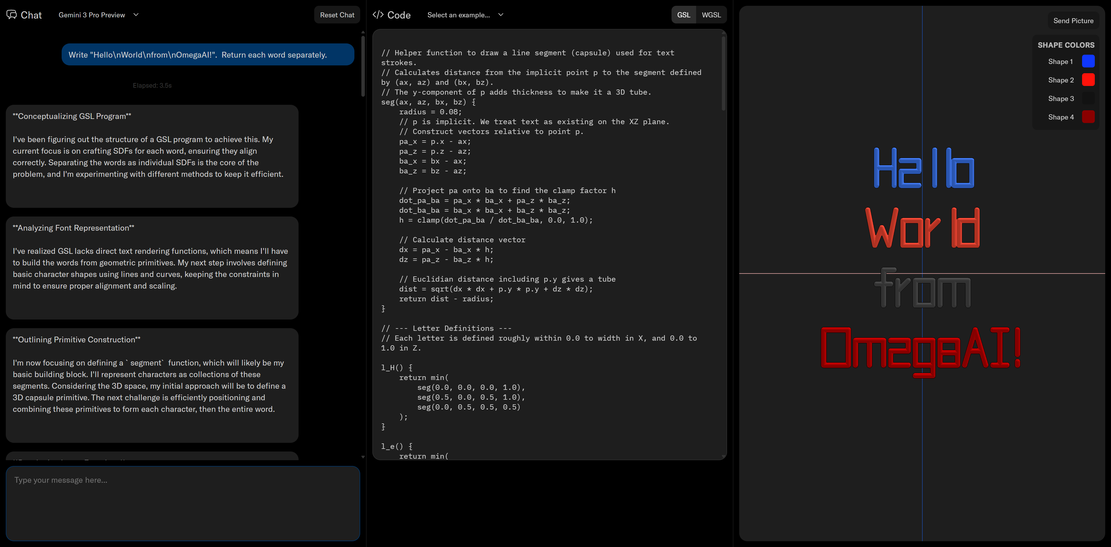
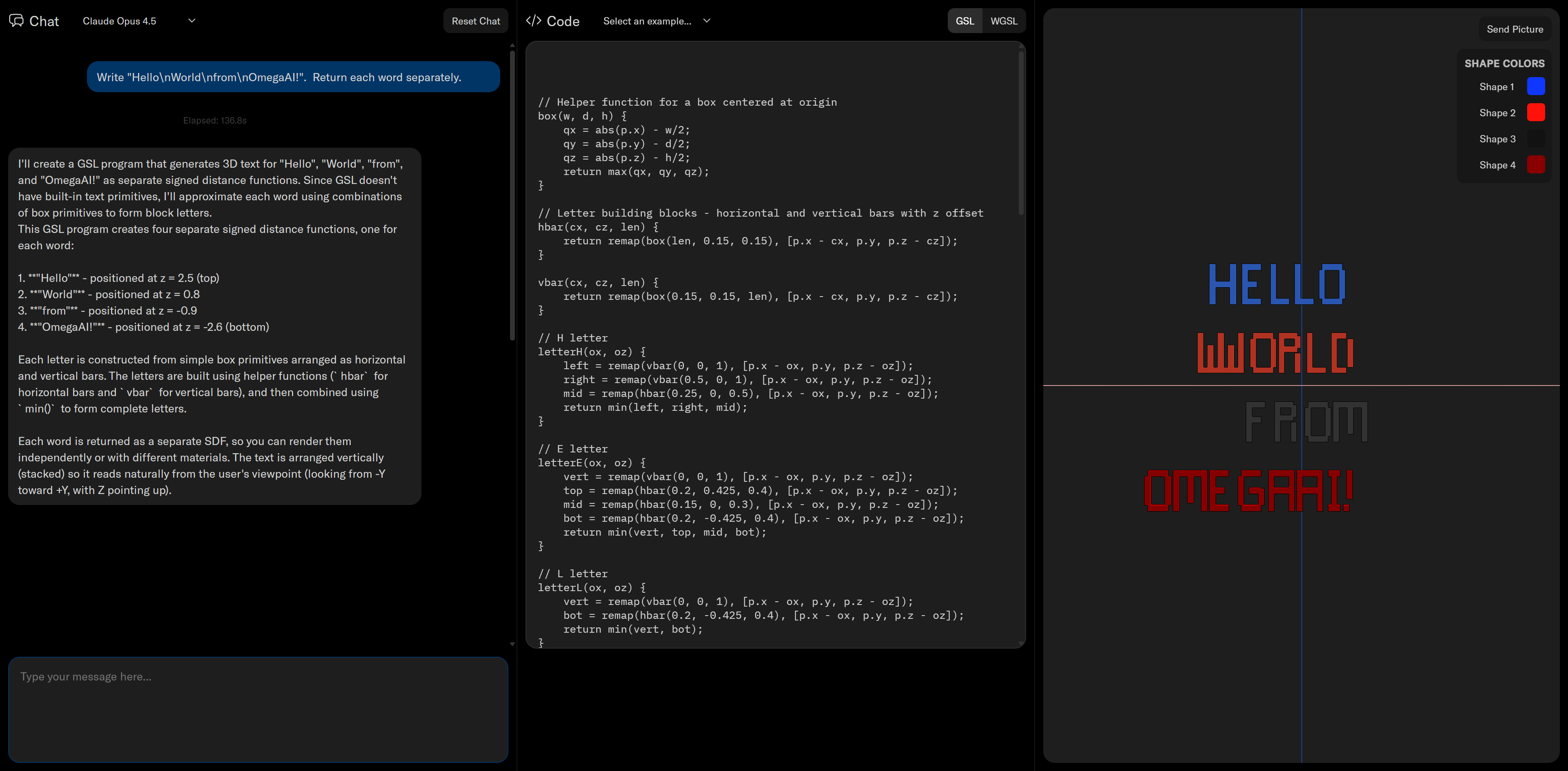
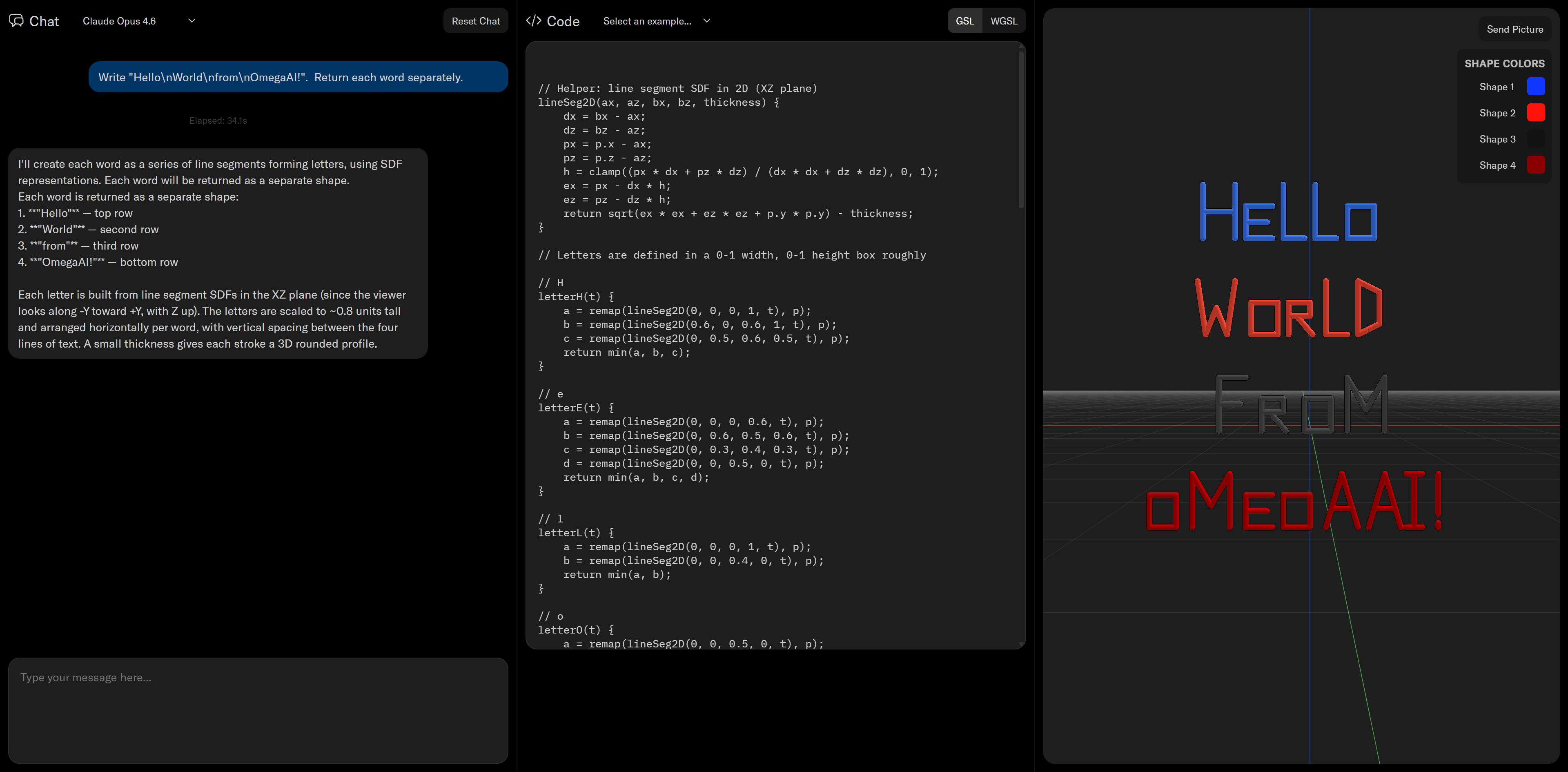
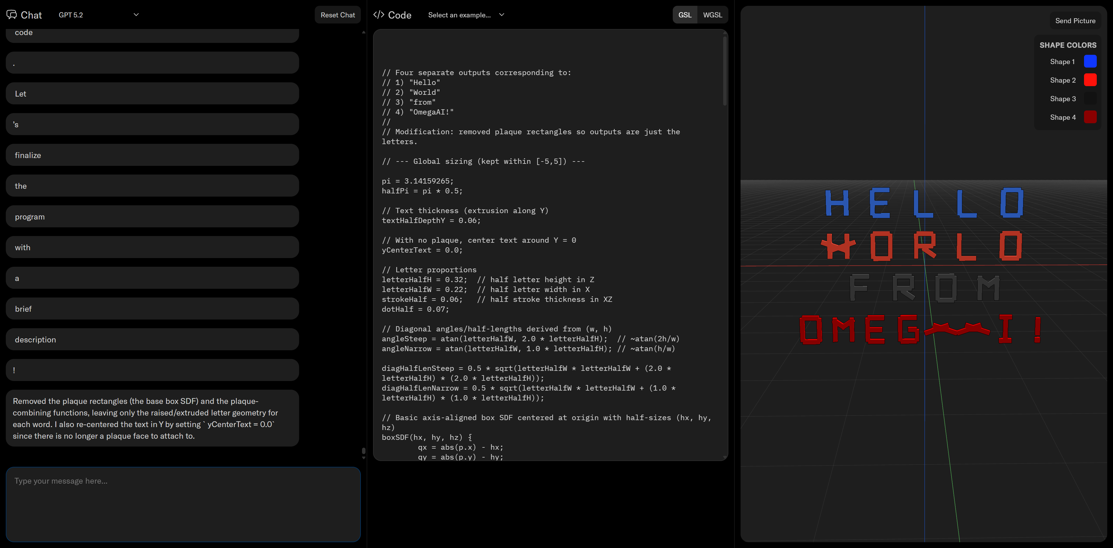
- Traditional “geometry as data” challenges AI and ML engineering applications because the model needs to anticipate the behavior of quirky geometry kernels.
- Geometry as code replaces the kernel with programmatic functions that encode geometric behavior and are much more amenable to AI and ML tools.
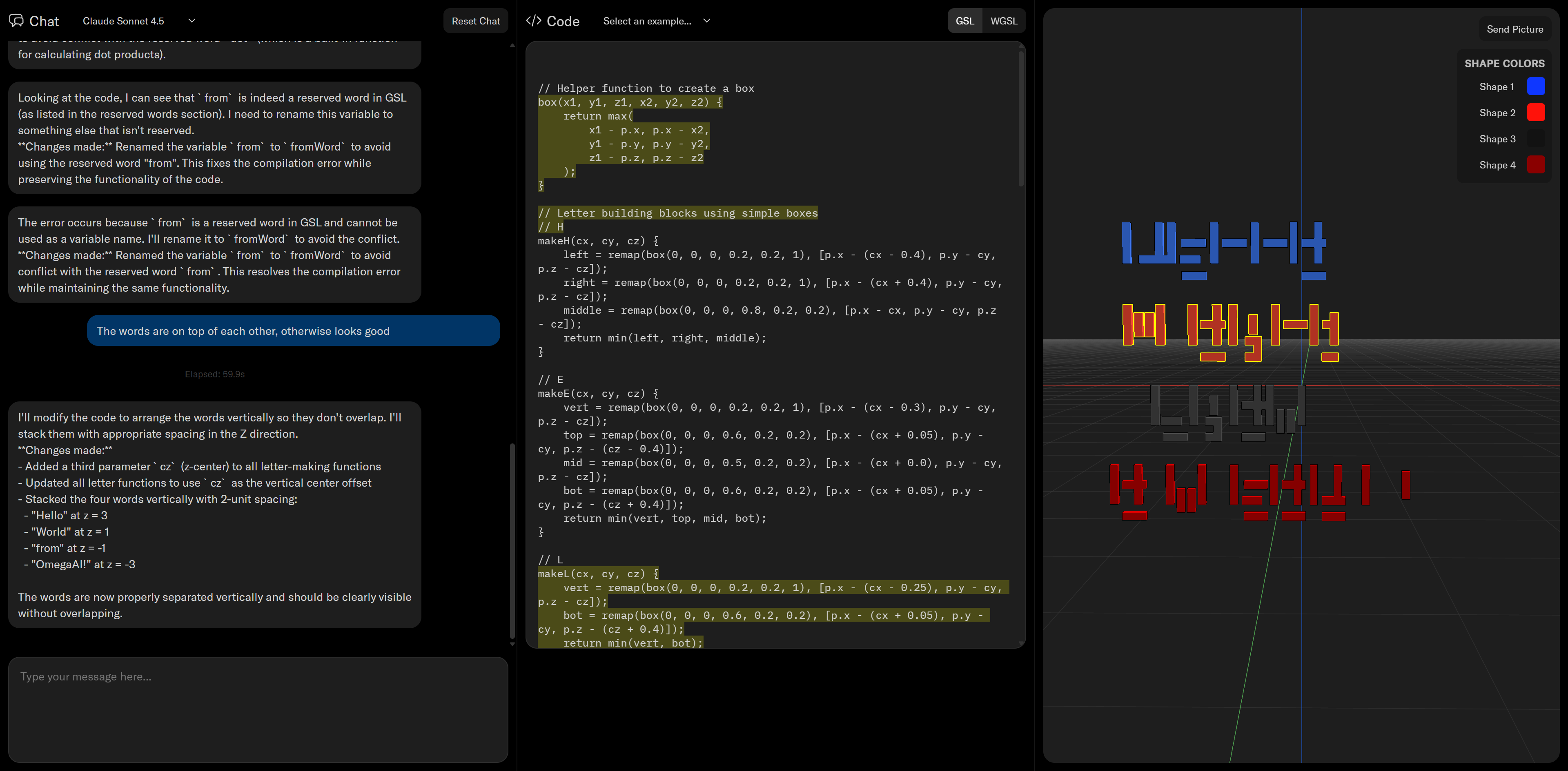
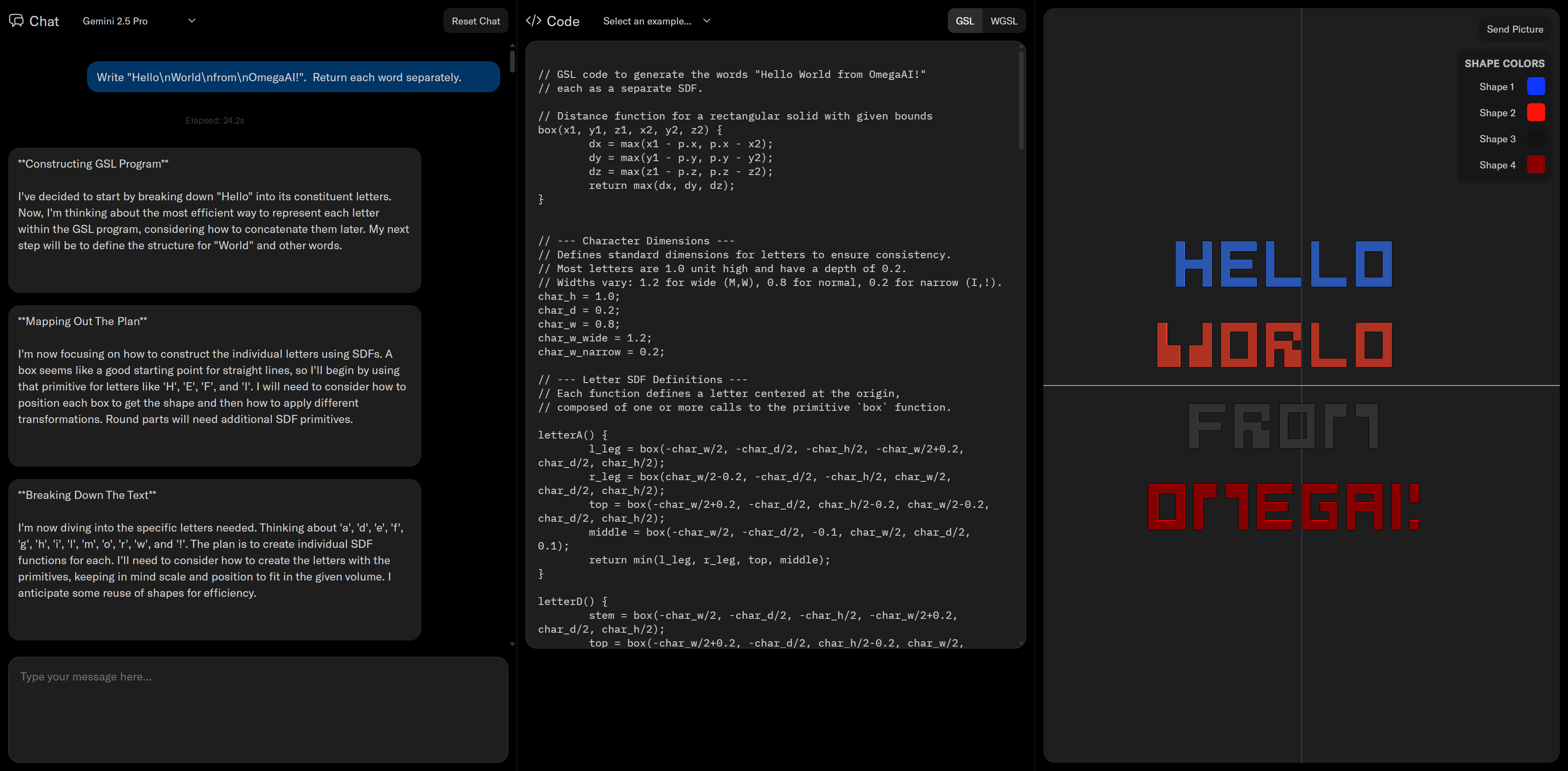
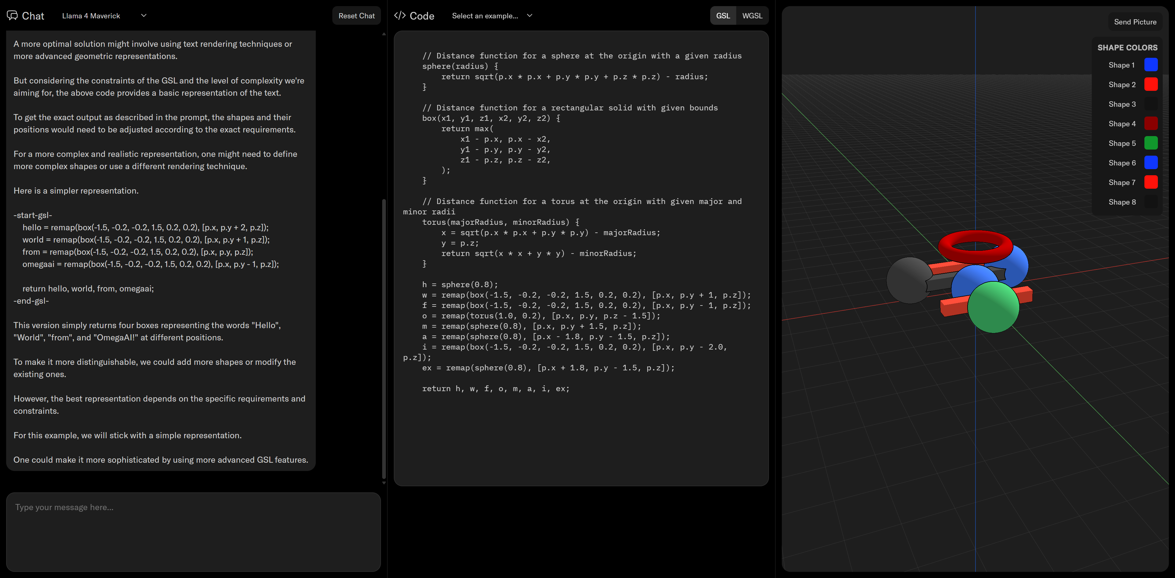
- Gradient Control Laboratories announces Omega, the world’s first pure geometry as code development system for engineering applications.
Background
Almost three years ago, Jeremy Herrman introduced me to the founders of Cursor, who eventually made what we now know as a wildly popular AI-powered IDE. In those days, however, they were attempting to create a “GitHub CoPilot for CAD” by training their tech on feature-based CAD models from OnShape and GrabCAD. They wanted to know why their models weren’t converging. Why weren’t there enough patterns in the CAD models’ construction to learn to autocomplete?
Within six months of starting my career at PTC three decades ago, I became aware that there was little engineering in CAD. I had joined PTC because I thought that by selling Pro/E, I’d survey the engineering disciplines and learn how engineers design. Instead, I learned what drafters do: create technical drawings that get passed downstream for manufacturing and archival. The actual engineering knowledge, the why behind the design, was nowhere to be found. Where did it live?
Thirty years later, we’re still searching for this mystical “design intent.” Our most sophisticated 3D models are still just collections of lines and curves with no understanding of their purpose. They’re documentation tools, not intelligent systems. Meanwhile, engineering knowledge remains inaccessible in Matlab and Python scripts, FEA decks no longer run in the latest codes, and real knowledge is lost to a diaspora of Office documents that may or may not be in PLM.
The team at Cursor reapplied their LLM tech to IDEs and built one of the most successful startups in recent memory. If we could represent geometry as code, could we perhaps achieve a Cursor for CAD?
At Gradient Control Laboratories, we are building Omega: a new suite of modeling tools for CAD that manipulate geometry as code. With Omega, engineering knowledge becomes portable, reusable, and understandable by AI. CAD models become free and open software that places equity with creators, just as IDEs do for software developers.
A Brief History and Future of Generative Design
Thanks to a prompt from Synera, for the Future of Engienering Summit I’ve assembled a historical perspective on both the technology and user experience behind generative design to frame a conversation.
Spoiler: it ends with category theory.
Breaking the Bottleneck: An Interview with Aditya Raghupathy
Thanks Aditya for hosting on your ongoing series Breaking the Bottleneck.
Geometry as Code: Blake Courter’s Blueprint for Implicit CAD
“With implicits, construction is transparent to the user; the kernel’s job is to render and convert back to B-reps, so the modeling tech can live in user space and geometry becomes open-source code.”

Joining Spectulative Technologies' Brains Accelerator
![]()
As Gradient Control Laboratories has become fully consumed with projects, we’ve started to consider how we might broaden our impact. With the future of engineering software in mind, we’ve joined the Speculative Technologies “Brains” accelerator program for feedback on some of our more ambitious thoughts.
Speculative Technologies Newsletter: Meet the 2025 Brains Fellows
Am thrilled to become part of such an inspiring peer group and mentor team.
Agentic Engineering: how AI automata will participate in engineering in 2025
At Gradient Control Laboratories (GCL), we have the privilege of seeing patterns emerging among the most innovative engineering software startups. Last year, we tracked the rise of differentiable engineering as the first differentiable CAD and CAE APIs appeared. Now, as we wire AI agents into PLM and BIM architectures, we’re ready to share our expectations for 2025 and beyond.
This post originated from conversations with Luke Church, GCL and Brad Rothenberg, nTop. It now includes significant contributions and feedback from: Mark Burhop, Sciath aiM (from whom we anticipate a nuanced paper on this topic); Jacomo Corbo, PhysicsX; Kiegan Lenihan, xNilio; Peter Harman, Infinitive; Saigopal Nelaturi, C-Infinity; Hugo Nordell, Encube; Alex Huckstepp, Uptool; Neel Goldy Kumar, Intact Solutions; Blake Reeves, Pasteur Labs; Andy Fine, Fine Physics; Kyle Bernhardt, Collectiv; and Claude 3.5 Sonnet.
Executive Summary
The future of AI in engineering won’t arrive as a single superintelligent design system. Instead, 2025 will see the rise of specialized AI agents that work alongside engineers throughout the product lifecycle — simulating assemblies, automating documentation, optimizing components, and configuring supply chains. These agents, operating both within existing tools and through new platforms, represent a fundamental shift in how we develop products, one that promises to dramatically accelerate and enhance the engineering process. Success will require solving key technical challenges around security and agent coordination. GCL is convening industry leaders this spring to tackle these challenges together.
Vision
The engineering industry’s vision for AI-powered design tools seems to mirror science fiction, from Star Trek’s Holodeck to Tony Stark’s workshop. The narrative follows three steps:
- An engineer declares intent, describing a design objective, its constraints, and performance goals;
- The computer synthesizes a complete design proposal, from geometry to materials to manufacturing; and
- Through rapid iteration and feedback, the engineer and AI converge on an optimal solution.

The crew of the Enterprise collaborates with The Computer to reconstruct a medical table in the Holodeck. Although this episode of TNG jumped the shark, this scene influenced me greatly.
Manufacturing Spaces Podcast
Had the pleasure to sit down with Em and Pete to discuss the future of CAD, with a focus on implicit modeling.
— emm0sh (@emm0sh) September 19, 2024
52 post articles, 7 pages.