Something seemed different about Sarah Frisken and Ron Perry, researchers from MERL who had ventured out to Boston’s Route 128 tech corridor to present their new modeling technology to the top geometry engineers at a leading CAD company. Frisken and Perry demonstrated that their adaptively sampled distance fields (“ADFs”) encoded geometry in a way where the offsets, Booleans, and rounded blends that confounded contemporaneous CAD systems like ours, would always succeed. They demonstrated organic texturing and lattices that would be unthinkable on state-of-the-art boundary representation (B-rep) solids. On the other hand, the modeling operations seemed limited to CSG operations, which had been superseded in mechanical CAD by the more expressive B-reps, and their only practical output was meshed geometry, considered inferior to B-reps. Would it be possible to combine the benefits of B-rep modeling with robust offsets, Booleans, and blends? It was 2001, I’d never seen anything like it, and I was hooked.
About a year later, at the earliest stages of designing a CAD system that would become known as “SpaceClaim,” I caught up with Frisken and Perry, who were interested in better understanding the viability of ADFs in engineering applications. At MERL, Frisken and Perry mentored me in implicit modeling, and I had the pleasure of working with Kizamu, their prototype modeler that delivered real time interaction at remarkably high fidelity compared to the state-of-the-art “voxel” kernels in Electric Image Amorphium and SensAble Freeform. Although we established that ADFs were not ready for mechanical design, we gained enough confidence to pursue 2D applications. ADFs and derived technology flourished in 2D, proliferating in font representations promoted by (Agfa) Monotype that targeted mobile devices and in drawing applications such as Mischief, authored by Frisken and acquired by The Foundry.
In the 2000s, precise B-rep kernels saw significant development to enable interactive modeling. SpaceClaim and its cohorts’ direct solid modeling paradigm caused local operations to be exercised far more than the history-based approach, and vendors spent years gusseting their B-rep kernels for the purpose. Although B-rep modeling became much more robust, its boundary-based (Lagrangian) nature ensured that a long tail of edges cases would always detract from uninterrupted, interactive B-rep editing.
Direct modeling permitted a more flexible data model, and SpaceClaim’s architect, David Taylor, fastidiously and passionately built a beautiful API that was a sort of homage to B-reps themselves. Inspired by the first generation of generative design tools such as Grasshopper and artists such as Jessica Rosenkrantz and Jesse Louis-Rosenberg at Nervous System and implicit art pioneer Bathsheba Grossman, I attempted use the API to produce generative art on top of B-reps, but became frustrated as I only further exposed their weaknesses. For example, to successfully union a few thousand cylinders of identical diameter into a lattice requires adjusting radii by microns to enable some Booleans to succeed.
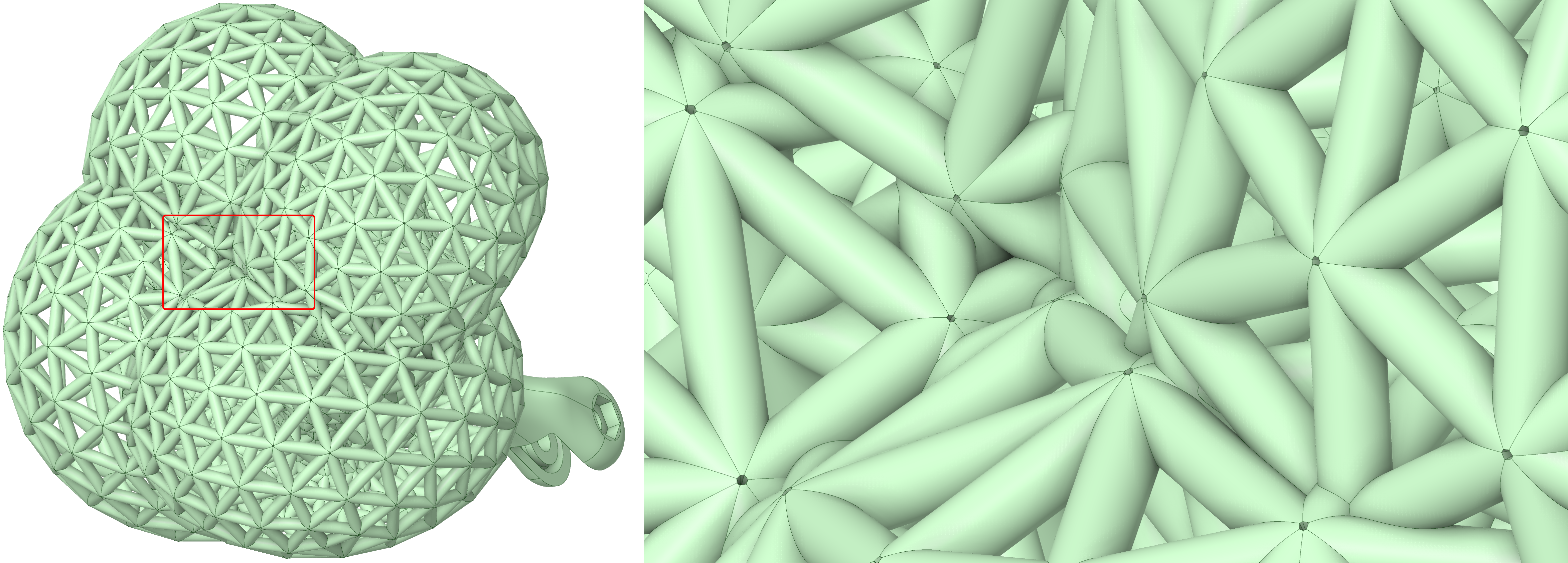
This boundary representation, produced from the edges of the non-manifold mesh, contains 8760 faces, 24,270 edges, and 14,181 vertices. About two-thirds of the faces are small triangles producing features below fabrication resolution. To successfully boolean this solid shape in a contemporary B-rep modeler, the process must be decomposed into a sequence of unions of subsets of the initial shapes, and some faces must be slightly offset to remove singularities. This geometry, the mesh of a Boy’s surface, is derived from the optimal minimax eversion by Francis and Sullivan and was modeled and rendered in ANSYS SpaceClaim.
Photon
In 2014, the 3D printing juggernaut Stratasys acquired the incredible team at GrabCAD, with whom I was proud to serve, and provided the challenge of making their prototyping technology more suitable for end-use parts. Few tools were available at the time that would permit volumetric control of structures, but ImplicitCAD and Monolith enabled the creation of some spatially varying lattices using simple distance functions, generating compelling results at small scale.
In June of 2015, our head of software, Jon Stevenson, introduced me to a hardware research team working on an electrophotography-based printer that needed their soluble support structures to dissolve faster. They were printing model material inside a solid block of support material, so we discussed adding lattices that would transition to solid near the part. Although I wasn’t sure at the time how to construct a distance field even in 2D, I was able to hack a simple slicer out of a GPU-based art project and compute a distance-like field by applying Gaussian blur to cross sections of a mesh, which could then modulate implicit gyroids. While the slices looked decent to me, the hardware team was initially underwhelmed, as they also needed the supports to transition to solid beneath the part. Fortunately, I was aware of the existence of depth buffers, and somehow produced a stack of slices by combining the depth buffer and Gaussian blur into a pseudo-2.5D distance field. The team fabricated a part using the first set of slices delivered, which printed successfully with supports dissolving orders of magnitude faster than before, removing a serious business impediment. We named the new slicer “Photon.”
The next week, I found myself talking to a different team on the other side of the world with a novel two-material system that required printing a minor fraction of support material, or a step of their process would explode. The code base of the old art project already dynamically loaded the shaders doing the heavy lifting, so I wrote a new shader that used the pseudo distance field (with a second depth pass from the top) to modulate subdivision of space-filling solids with thin gaps. The first prints from this approach were also successful.
Having supported two hardware teams on a whim, I sheepishly approached GrabCAD’s head of engineering, Amos Benninga, to inform him of the liabilities I’d potentially created. He was delighted, and offered me a small team if the stack could also support PolyJet, Stratasys’ flagship multi-material jetting technology. The next day, I handed him a Photon-sliced PolyJet part.
Steve DeMai joined as lead engineer on Photon, evolving it from a Node/Electron art project to a professional, optimized C# application. I figured out how to replace the Gaussian blur with a narrow-band distance field by brute force sampling, but performance was terrible. Steve implemented several methods, ultimately landing on the sweep-based lower envelope distance algorithm and, with Nur Arad, realized he could precondition it with the depth-buffer, giving us a full resolution, accurate, signed 3D distance field of entire slices in real time.
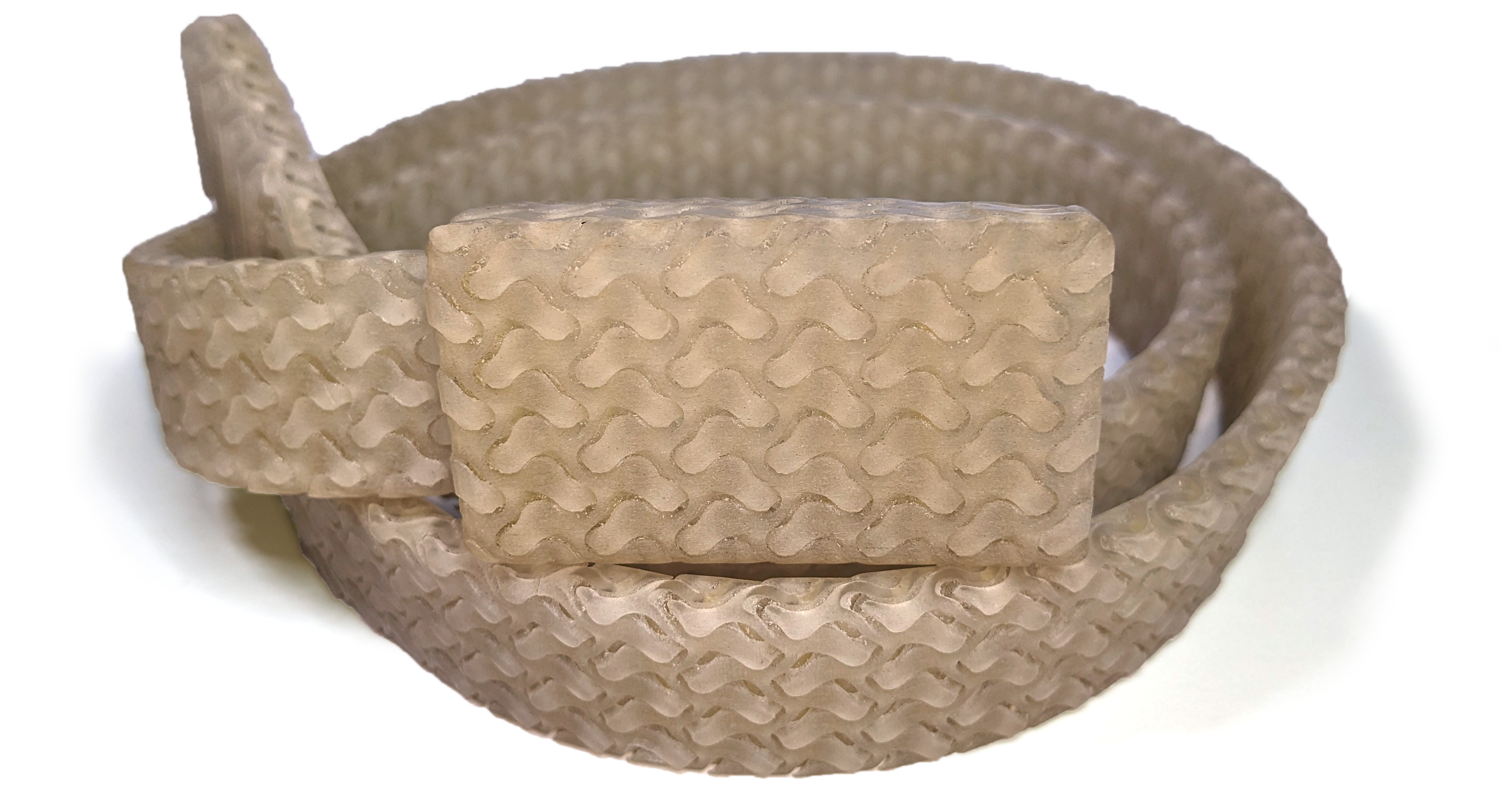
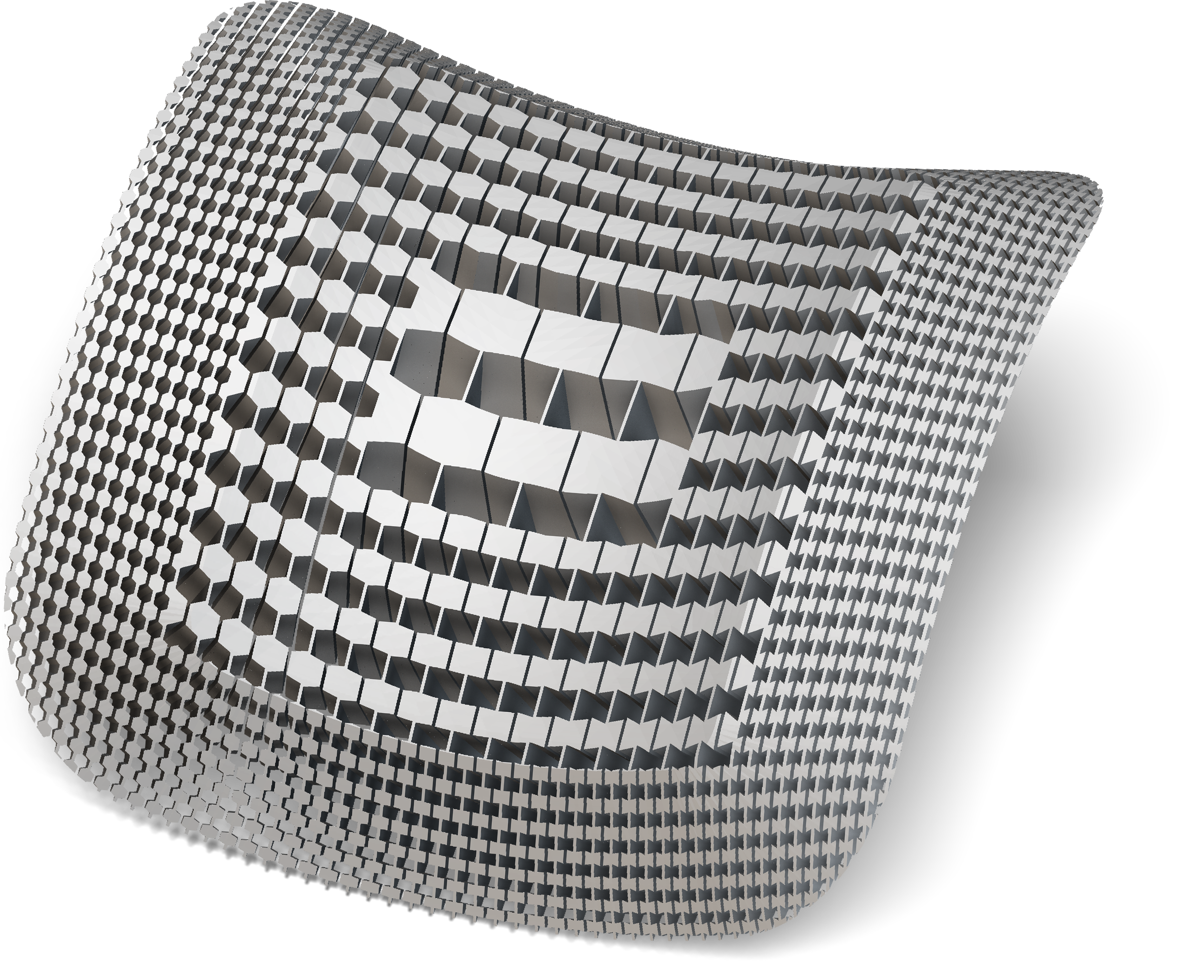
For this limited compliance assembly, the untrimmed individual repeating unit was produced with Monolith, then assembled, trimmed to shape, and packaged for manufacturing in SpaceClaim. (We’ll eventually get to a post on such ramped, folded structures.)
As far as I’m aware, this was the first point in history that an implicit modeler produced distance fields from imported meshes at the full resolution of high-fidelity manufacturing hardware. It’s a moment I had estimated far further into the future, but made possible by the hardware’s relative coarseness compared to traditional manufacturing processes. As impressive as PolyJet’s 600DPI resolution may have been, the \(~40\,\mu m\) resolution is about two orders of magnitude coarser than the worst case in most engineering software implementations. Over three dimensions, and coupled with the fact that we only needed to slice as fast as printers could print, our modeling stack delivered end-to-end results with eight or nine orders of magnitude less computing than I’d predicted. The future was now!
While Photon’s main job was to prototype techniques to slice parts, generate supports, and produce output for novel printing processes, my interest lay in generative solid modeling. Our team had two interns just out of high school, Brenna Sorkin and Bradley Stevenson, who started implementing our modeling library. Brenna sorted through Vadim Shapiro’s notes on Rvachav’s R-functions to implement blends, and Bradley found expressions for primitives that somehow had more if statements than the primitives had topology. The art project had a bunch of noise functions copied from all over the internet, which combined with periodic lattices, TPMS such as gyroids, and Brenna and Bradley’s contributions, constituted a pretty awesome modeler. Much of that prototype library gave way to Inigo Quilez’s elegant haiku of distance field primitives, about which I was oblivious until at least 2016.
With three bitmap-based printing platforms initially supported, we hooked up marching squares and cubes to produce high-resolution output for toolpath-based printers and CAD. There was strong affinity with Stratasys’ need for novel support structures and my interest in applying generative thinking and implicit modeling to mechanical engineering challenges. New materials and hardware configurations created endless demand to create more slicers that could synthesize supports and fine-tune process issues. Creating working hardware and electronics was typically the main concern of the engineering teams, so I found myself not only producing slices, but also working through the process engineering, a discipline rife with contradictions and exceptions. (For example, it’s common to both want to support a model from below and also create an in-layer air gap between the model and support materials. In regions with sloped overhang, there’s a contradiction between the air and the supports, and different process situations call for different choices.)
Support structures require precise control over offsets and taper, some of the most error-prone operations in traditional B-rep-based CAD technology, so we developed techniques to handle them correctly. Challenges like the H-2000 prototype separated the problems of gravitational and build process continuity, resulting in support geometry that resembled multi-pull injection molded parts. Meanwhile, we had other interesting challenges that weren’t easily described with conventional distance fields, like needing to know the distance from the silhouette of the projection of a shape to create the coated PolyJet supports.
Only armed with signed distance fields, we would have been forced to approximate some of the fields needed to construct these results. Coincidentally, the intermediate data Photon used to construct the 3D distance fields also facilitated computation of the needed auxiliary fields. For example, in the process of building the 3D field, we could also generate the 2D distance field of data only on the plane. Using the depth buffer information, we produced a 1D signed directional distance to our shape from above or below. Similarly, we could construct a distance to the contour or the silhouette in a given slice plane. These “foliated fields” (future post) became indispensable in enabling draft and making appropriate choices in situations like the underhang contradiction mentioned above.
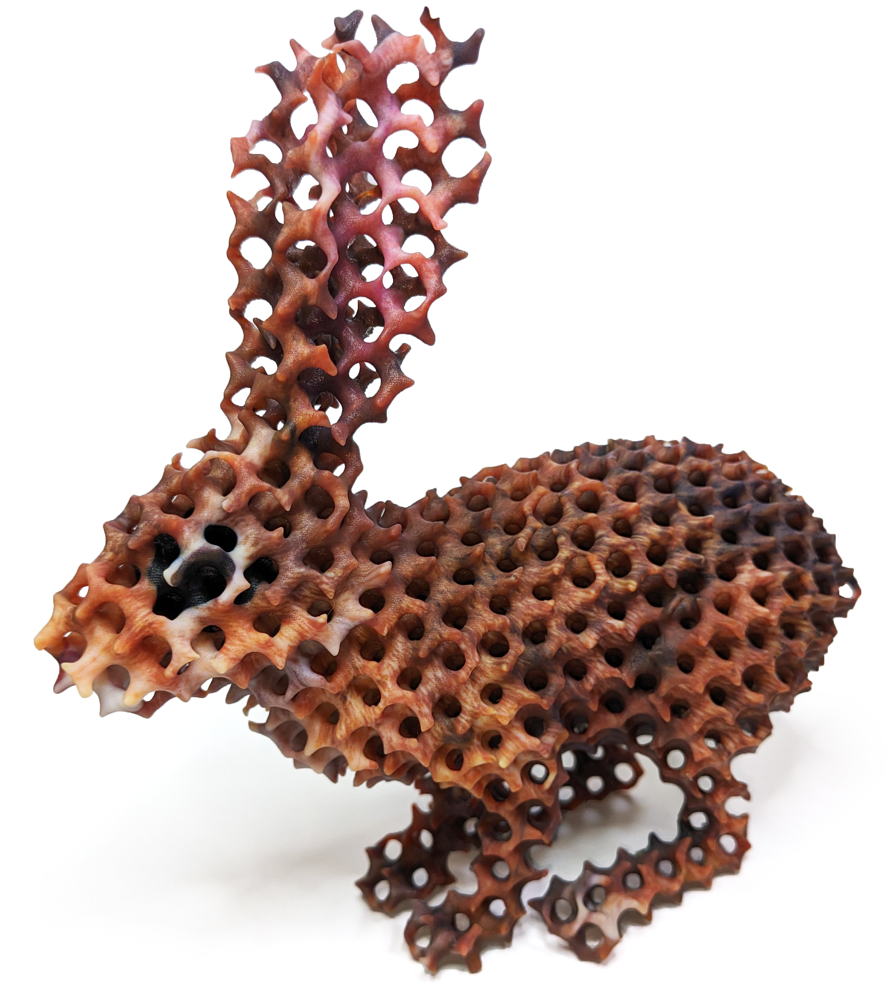
A texture-mapped rabbit (right) intersected with gyroid TPMS, with the intersection blended, and printed on a Stratasys PolyJet jetting system with five color resins. The original model is a sample provided with Materialise Magics software and was sliced and rendered with Implicit Space (right).
For each of these these fields, Steve had provided a data structure that included not just the distance, but also the closest point and therefore the gradient. At the closest point, we knew the surface texture color, surface normal, and ID of the body and face topology. We could support an arbitrary number of juxtaposed fields for different bodies or body types. When manual input was required in delicate processes, we could easily tune the builds using color maps or 3D Photoshop jobs. Each slicer could be configured with custom parameters and options to enable a surprising amount of control and interactivity.
The ultimate application of Photon came from Daniel Dikovsky, who had been experimenting with a family of eight PolyJet materials that, when printed together, could reproduce the material properties of human bone, soft tissue, and blood. We would layer low-fidelity, segmented MRI data of organ structures, assign each layer a tissue type, and paint on layers of embellishment as needed. The biomimetic slicer would then add mesoscale structure, interpolate it between the layers of geometry and modulate it with metadata fields, knitting together complex assemblies of organ structures. The geometry would often be imprecise and overlap, and we often needed to fix clearance and interference between the meshes. It was in this setting that I first started to compare distance fields, investigating the difference field (midsurface), sum (clearance), and their ratio, the “two-body field” that interpolates between shapes (topic of next post). We were quickly achieving results that would have been inconceivable with meshes alone, such as automatically dilating small vasculature to meet minimum manufacturing conditions or designing intentional structural defects to mimic pathological situations.
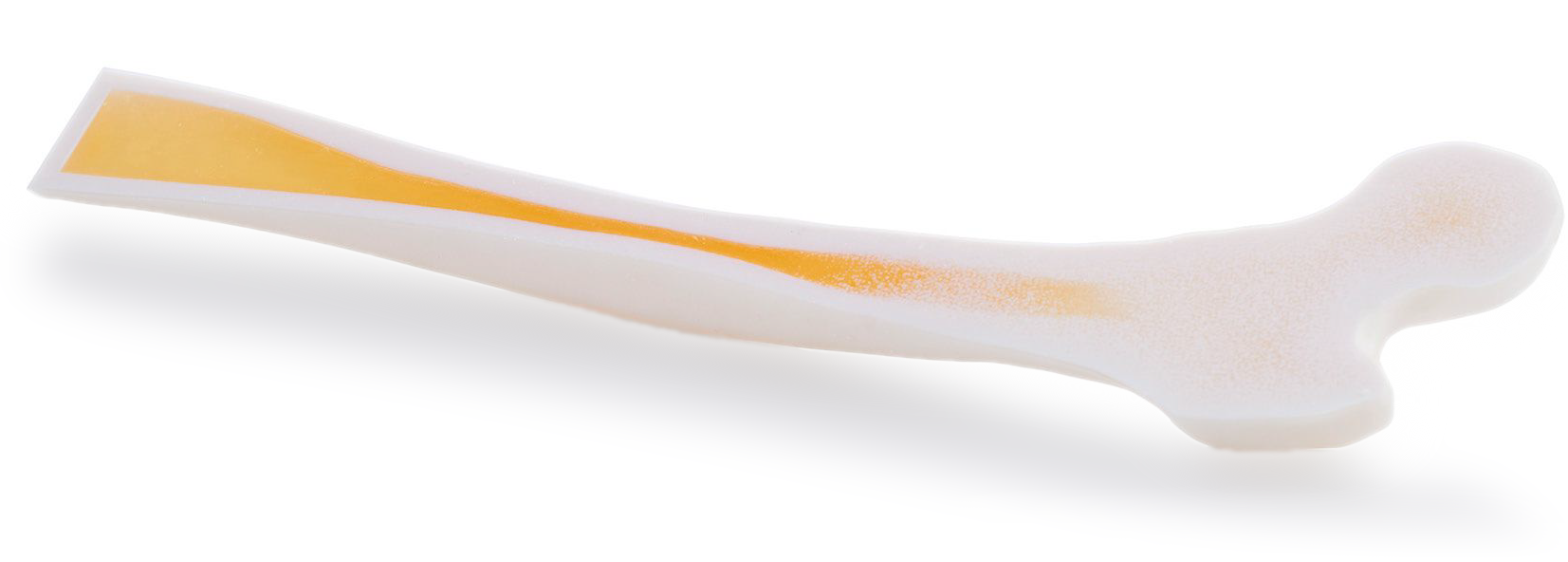
A biomimetic femur produced with prototype software and materials of the Stratasys PolyJet Digital Anatomy system. The wall thickness varies along the length of the bone, and the trabeculae (lattice) on the proximal epiphysis (round end), which would be too fine to produce at scale, are homogenized via cellular (Worley) noise.
Eventually, we also solved toolpathing, cost estimation, color calibration, and material property management challenges in Photon, much of which lives on in Stratasys’ commercial products and its spinoffs.
nTopology
In the spring of 2017, I met Bradley Rothenberg, founder of nTop (née “nTopology”), at the COFES gathering of engineering software technologists. nTopology’s first product, Element, was a runaway success for latticing 3D printed models, and Brad was interested in expanding the vision to a broader set of applications. I started to advise the company as they were raising their A round, and we upgraded the pitch to generalize generative technology beyond additive. With funding achieved, I visited nTopology’s original office on Lafayette Street in SOHO, New York City, to help align product strategy to the expanded scope. Element had been hitting a resolution wall with the popular and excellent OpenVDB kernel, so we had a whiteboard discussion over the advantages of B-reps, meshes, and implicits. The team decided to give implicits a shot, creating a beautiful block-based user experience with evaluation initially powered by Matt Keeter’s libfive library.
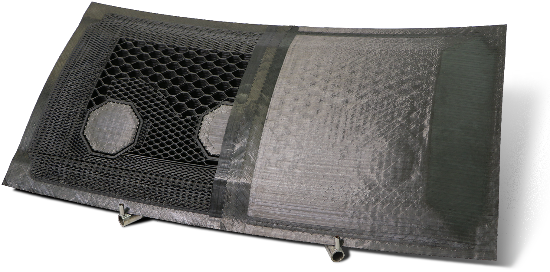
An application of UGFs on spatially-varying, multiscale, geometry designed for 5-axis deposition and created and rendered in nTop (left), and an example from industry produced by Electroimpact SCRAM. UGFs maintain constant gaps between walls while the surrounding geometry is warped into a curved space, the map of which is defined by a distance field and two orthogonal two-body fields. This nTop demo video demonstrates the approach.
The results were impressive, as nTop could render in seconds 3D models that would take Photon hours. I joined full time to build nTopology’s product team and ready the product for market before settling in as CTO, where I spent most of my time applying “nTop” to diverse mechanical design challenges. nTopology’s engineering team continued to accelerate performance and increase resolution, and the flexibility of the block system enabled us to quickly prototype new applications.
The initial set of nTop implicit modeling routines included a decent set of primitives and blended Booleans that still represent the state of the art. As with Photon, careless use of these blocks would produce unintended results. While implicits may never fail, garbage in is still garbage out, perhaps without the error message one would see doing something similar with boundary representations. Just as with SpaceClaim, where interactive modeling exposed weaknesses in the B-rep paradigm, nTop’s expedient user interface and diverse user base exposed usability issues with implicit modeling. Without care, common modeling operations such as offsets, Booleans, and blends, while unbreakable, can leave unexpected artifacts in the remote field that may appear as defects in subsequent operations. In addition, popular implicit fields like gyroid lattices are not distance fields, creating further aberrations. To make implicit modeling accessible, nTopology created specialized tools that do the right thing in everyday workflows.
Unit Gradient Fields
Over time, as engineering tools become higher fidelity and increasingly interactive, they propel their users to higher vantages from which they gain better control over their work. When waiting overnight for a result, as with Photon, the surprise of an oddly-shaped blend causes less notice than in real-time physically-based rendering in nTop. When making support structures and mechanical demos with Photon, such details were negligible, but when designing real parts in nTop, they were hard to avoid. With the initial focus on latticing and topology optimization use cases, the core tool in nTop delivered results, and several of us strove to facilitate trickier situations such as modulating warped lattice parameters.
To work around early performance and limitations in nTop that have since been overcome, I prototyped a new gradient-aware stack on top of a new project Steve DeMai was interdependently pursuing, “Implicit Space”. (The work was sufficiently contemporaneous with Quilez’s post on gradients that I yet again just missed using his results.) Over a few releases, nTop received more tech to compensate transformations, culminating in a new pipelines that abstracted the grunt work of modulating warped lattices. With a “new lattice pipeline” and breakthrough interactivity in nTop’s third release in the spring of 2021, nTop felt like a complete product for lattices and top opt. Although there wasn’t a single technology that addressed the issues, a common theme became keeping the gradient magnitudes (Lipschitz coefficients) near unity.
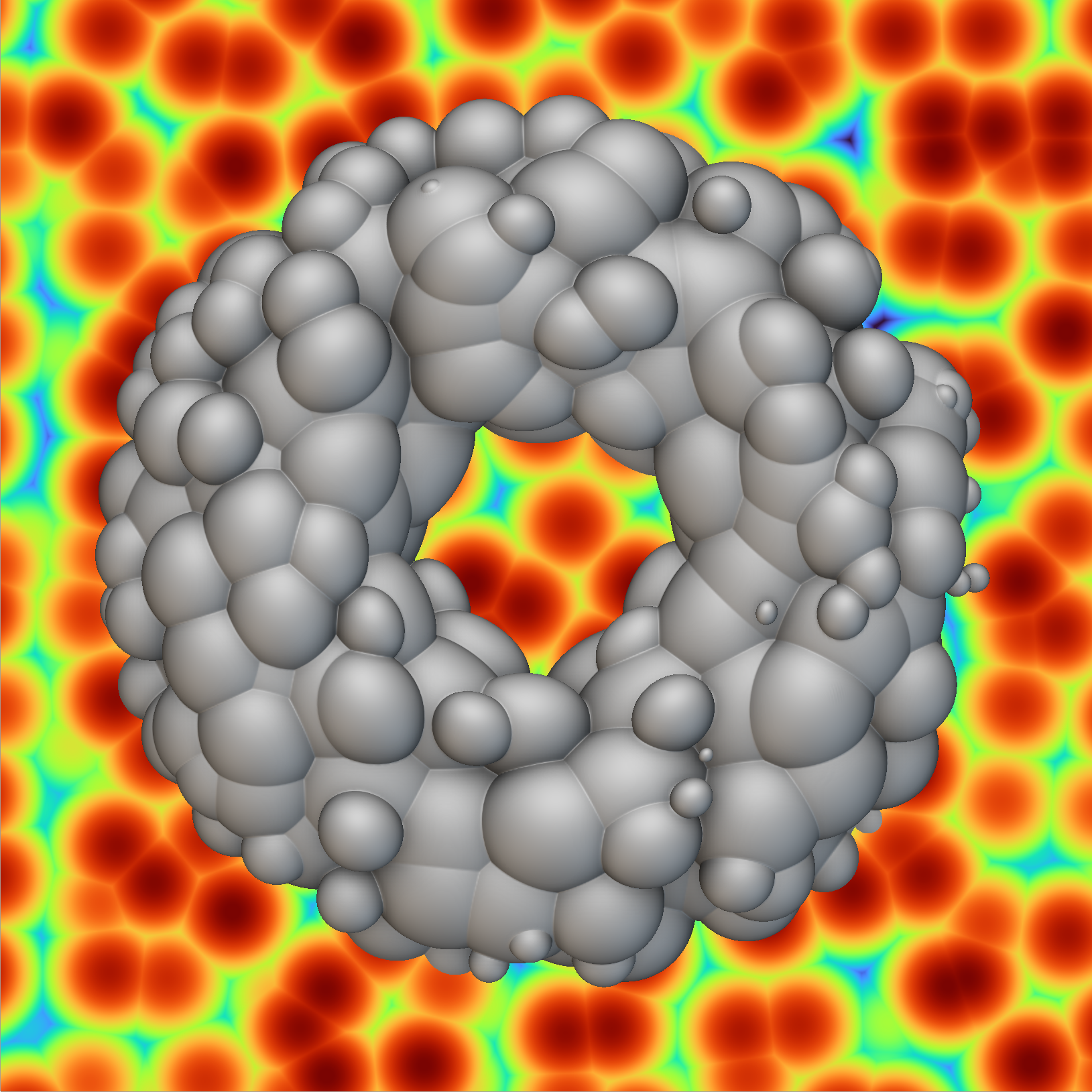
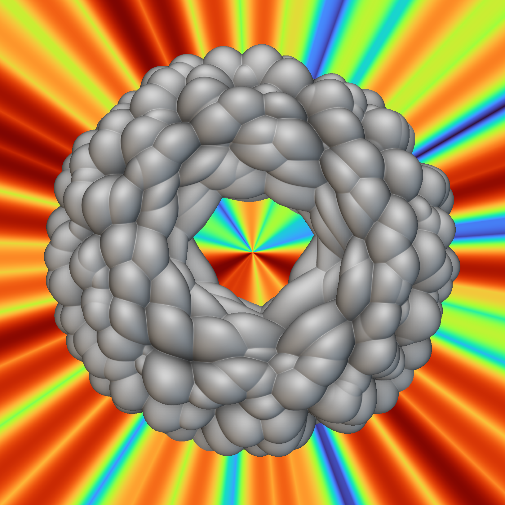
A Worley noise field displaces a torus. On the left, there are overhangs with respect to surface torus gradient and disconnected topology. On the right, the noise field has been composed with the torus’ boundary map, so no overhangs or disconnected topology are present.
Through the COVID years, I dedicated more time to working on recapitulating the full suite of rounds, chamfers, and drafts expected in conventional boundary representation modelers for mechanical design. Although the \(\func{Radiate}\) operation (remapping through via the boundary map) had proved useful at Stratasys for monotonic texturing, I found it could construct isocline draft surfaces as well as rolling-ball rounds via what I would learn to be called “the normal cone” (last post). At the time, the constructions were missing the correction factors needed to conserve unit gradient magnitudes, so I reached out for assistance to Vadim Shapiro, the peripatetic professor from UW-Madison, CEO of the pioneering simulation startup Intact Solutions, and editor of The CAD Journal. For over a decade, Vadim has helped fill gaps in my analytical acumen while I’ve provided business advice to Intact. He quickly responded to my long email which was brief on descriptions but included lots of pretty pictures of cross sections. His response was something like:
“I have no idea what you’re talking about.”
So I tried to explain a bit more about the radiated field construction, because I thought I was just looking for a bit of standard differential geometry. However, he replied with:
“I still have no idea what you’re talking about, but your techniques appear to be new. It sounds like you are trying to say something like…” and he proceeded to state a little proposition and a proof. “You need to write a paper. Let’s talk on Monday.”
On Monday, Vadim started to cajole me into this project. He promised to help, but only if I stopped sending him rambling emails, typeset everything in \(\LaTeX\), and produced a paper. He foretold that with this endeavor, I would achieve a much clearer understanding of the concepts and produce higher fidelity results. I spent the fall of 2022 and winter of 2023 expanding this “paper” to a somewhat technical manuscript, which feels like it’s about half done, but I keep finding practical and curious side roads to explore. Although the work so far has been receiving good feedback, most of my friends and colleagues prefer a simplified treatment, which is why I’ve decided to ship the most fun and useful parts of the book in these blog posts.