Executive Summary
- We compare and contrast two groundbreaking advanced manufacturing startups, Rapid Liquid Print and Variant3D, including the application, modeling approach, and product strategies.
- Discrete differential geometry has demonstrated its value in production-grade engineering software.
- Unit gradient fields abstract both signed distance fields and geodesic distance fields, making surface field modeling easier to use.
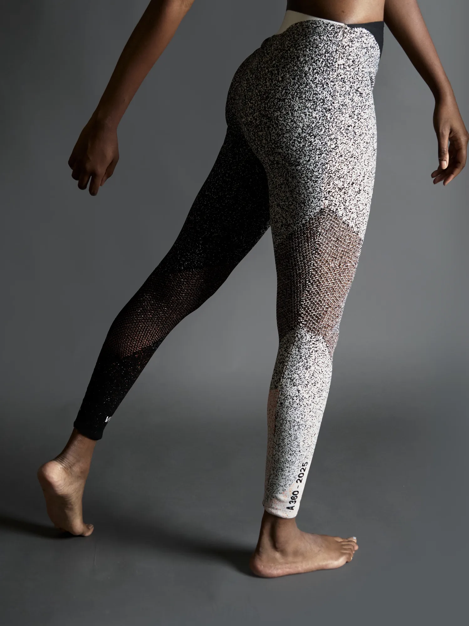
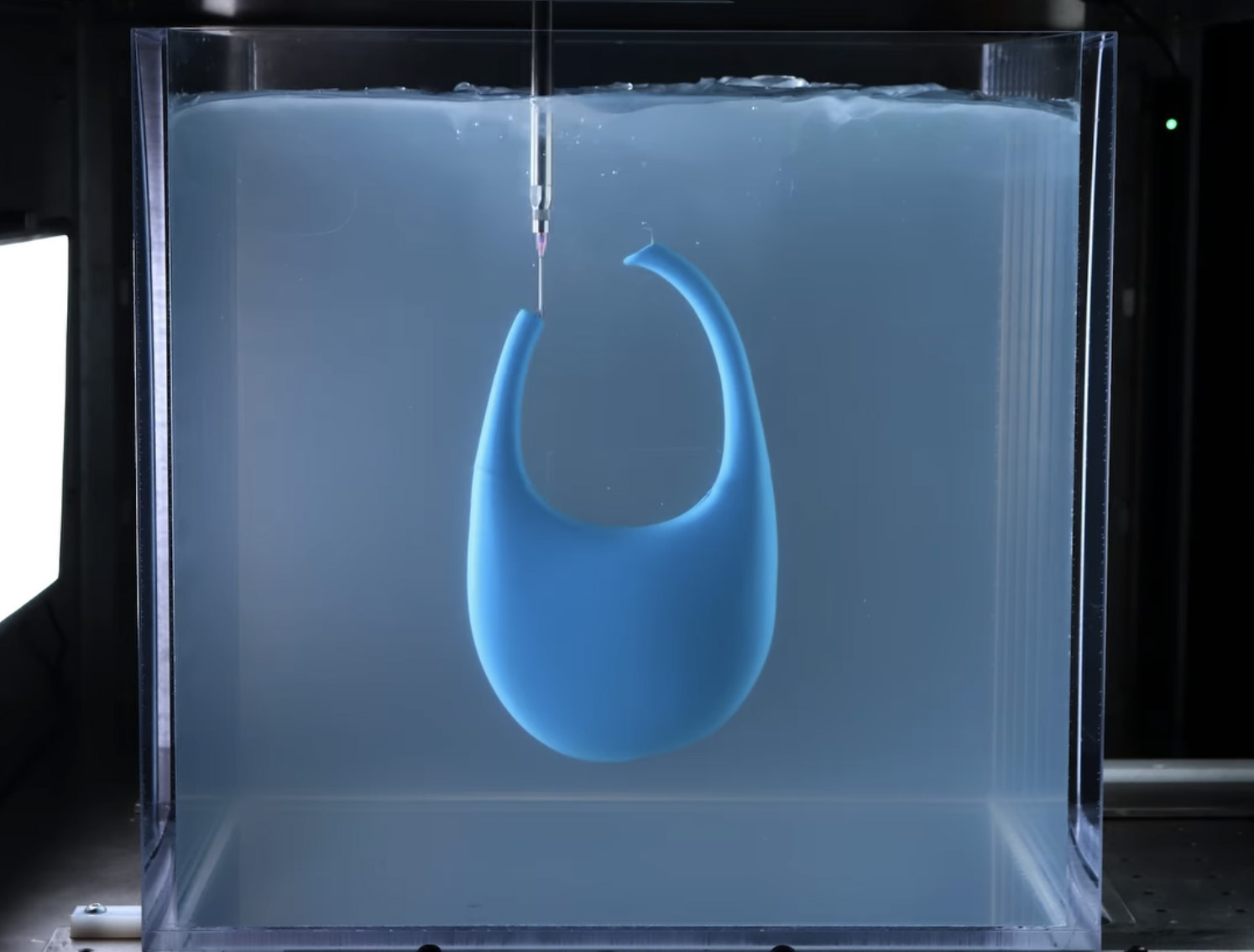
A knitted legging by Variant3D (left) and gravity free silicone fabrication for Coperni by Rapid Liquid Print (right).
Context
In the spring of 2024, Gradient Control Laboratories (GCL) had successfully incubated LatticeRobot and was building visualization tools for Alloy Enterprises (just acquired). After a conversation at the first CDFAM, Will Samosir at Variant3D (V3D), who had developed technology to knit arbitrary 3D surfaces, signed me up as an advisor, and Hamilton Forsythe at Rapid Liquid Print (RLP) reached out for thoughts on their 3D toolpather for gravity free printing. A pattern quickly emerged.
I was seeing:
- Two very capable designers,
- Who both figured out cutting-edge discrete differential geometry (DDG),
- Operating on open curved surfaces instead of the usual solids,
- To deliver functional prototypes,
- Built on academic, experimental research code that’s risky for production work,
- To enable unique manufacturing processes capable of fabricating arbitrarily curved surfaces,
- For which unit gradient fields (UGFs), my main research project, offers novel approaches,
- Not to mention the all-caps, four-letter brand names VEER and LOOP,
- With a double vowel in the middle,
- And companies who go by three letter acronyms
- Which is apparently appealing to their target audience of computational designers,
- And explains how they attracted similar name-brand customers,
- While refining innovative fabrication services into advanced manufacturing startups.
Although both Will and Hamilton were interested in applications of UGFs and my research field-driven design, more pressing matters such as product strategy, organizational excellence, and systems design quickly presented themselves. After meeting the leadership teams, including Garrett Gerson from V3D and Schendy Kernizan and Bjørn Sparrman from RLP, the GCL team joined both projects, and for about the past two years, we have helped bring LOOP and VEER to market. As a collective dedicated to incubating new engineering technology, we could not be more pleased with our contributions, both in these applications, the theories behind them, and the teamwork.
Let’s take a look at both products and study:
- The two manufacturing processes, their advantages, and possible limitations
- The kinds of fields each system produces, and why
- The audience and packaging for LOOP and VEER
Rapid Liquid Print
Rapid Liquid Print (RLP) spun out of the MIT Self-Assembly Lab in 2021 with a deceptively simple idea: extrude production-grade, platinum-cure silicone into a reusable gel suspension medium, effectively neutralizing gravity. The result is what they call gravity free manufacturing: supportless, non-planar, isotropic silicone parts that you print, pull, and rinse with water. No post-curing, no sanding, no chemical waste.
Their hardware platform, Levity, elegantly deposits platinum silicones ranging from Shore 00-50 to Shore 50A, with real-time material blending that enables multi-durometer and multi-color parts in a single print. The machines produce consumer goods, prosthetic liners, inflatable actuators, and vascular models for medical use.
RLP’s process excels at fabricating surfaces by extruding a continuous spiral toolpath, like FFF vase mode, but in 3D and on arbitrarily curved surfaces. The goal is to construct the highest quality spiral possible, then sequence multiple spirals together for complex topologies like handles or branching structures. RLP can also fill volumes with lattices based on surfaces or hexahedral meshes and add different kinds of surface texture.
VEER On (Online) is a cloud-based platform designed for operators on the factory floor who want a guided, linear workflow. Upload a mesh, click through process-specific parameters, and get a print-ready toolpath without touching any settings. It’s optimized for production: if you’re making 100 prosthetic liners a month, VEER On establishes a repeatable, scalable process.
VEER Off (Offline) is the Grasshopper-native version for computational designers who want full access to the underlying engine, advanced data, and the ability to compose VEER’s capabilities with anything else in the Grasshopper ecosystem or any advanced manufacturing process.
By building both on a common engine, we knew we could address any customer need: easy cloud software for production teams and expert desktop software for computational designers pushing the boundaries. See more from Hamilton and Kimball Kaiser’s presentation at CDFAM Amsterdam 2025.
Variant3D
Variant3D (V3D), founded by Garrett Gerson and Will Samosir in Malibu, California, has achieved something that the knitting industry once thought impossible: driving any flat-bed knitting machine directly from structures on a 3D surface, without the low-level, bitmap-driven machine instructions that have been the industry’s sole interface for decades.
To understand why this matters, consider the landscape. Industrial V-bed knitting machines are remarkably intricate devices. A carriage zips left and right across hundreds of needles, picking up yarn feeders (up to 16 materials) and activating needles according to machine instructions. But every one of these machines is driven by proprietary software that can only be understood by expert knit engineers. These engineers are a scarce, expensive dependency in the design cycle: a single iteration takes weeks, and designers and engineers negotiate through physical prototypes because they have no shared language.
Kniterate provides a simple example of a double needle bed knitting machine. Industrial machines typically run twice the size, weigh 10x as much, and include more than one “system” on the carriage to handle several actions in one pass.
V3D changed the equation. LOOP lets any designer assign directional parameterization to any input surface and visualize knit structures directly in 3D. The philosophy is simple: if you have a browser and a CAD design, you can knit it out. What previously required a knit engineer, a physical prototype, and three weeks of waiting can now be done in minutes.
Starting with Polyscope and Houdini for internal geometry research, Will and the team evolved through several iterations into what would be delivered in LOOP, using computational geometry to make 2D and 3D knitting accessible and even fun for designers. But only half of the solution could be delivered within LOOP. Not only were we the first to compile output directly to arbitrary knitting machines, we also integrated with scanners and 3D printers to create local knitting workcells for rapid prototyping, enabling breakthrough time-to-market for leading name brands who previously had to work with factories just to iterate on a design.
The knitting machines themselves have characteristic manufacturing constraints worth understanding. A V-bed machine has two needle beds (front and back) that face each other at an angle, with fabric forming in the gap between them. The carriage travels left and right, and at each pass, needles on either or both beds can be selectively activated. This gives rise to common structures: single jersey (knit on one bed) and double jersey (both beds), pointelle (decorative holes created by transferring stitches), ottoman (raised ribs), inlay (yarn laid between needles without knitting, for reinforcement or stiffness), and various channel and surface textures. Different hardware has different capabilities, including gauge (needle spacing), bed width, number of yarn feeders, and transfer capabilities all vary, while production knitting adds constraints around speed, tension, and takedown.
Closeup of needle bed knitting actions on a single feeder, single needle bed machine making single jersey. The hook-like objects are called “latch needles” and are driven by several cams, the action of one of which is seen at the bottom.
Will and the team at V3D launched LOOP at CDFAM 2025 NYC.
Let’s make a footwear upper
Although RLP and V3D make very different kinds of structures, they are both additive processes. When it comes down to build processing, there is only one main difference: RLP VEER is optimized for tubes. V3D LOOP is optimized for sheets.
To make a footwear upper, it means that for LOOP we are going to introduce a seam that would be periodic for VEER. In both cases, we will be constructing a new UV field on the surface, but using different techniques. To demonstrate, let’s use a tongueless upper as an example of a part that could be made with either process.
The parameterizations VEER and LOOP synthesize for build processing. Observe how LOOP generates near-orthogonal fields unaligned with boundaries, while VEER produces smooth transitions between boundaries.
The build processing coordinate system
In advanced manufacturing, the software that converts design geometry into machine instructions is called a build processor. In nearly every process, from FDM to SLA to knitting, two directions dominate the structure of the fabricated part: the build direction, along which the part is layered, and the process direction in each layer, along which material is deposited. In consumer 3D printing, these directions are trivially defined: the build direction is Z (fighting curl and gravity), and the process direction is an XY raster or contour within each planar slice. The mechanical properties, surface quality, and anisotropy of the finished part are all governed by the relationships between these two directions, material science, and the part’s geometry.
What makes LOOP and VEER interesting as build processors is that they abandon the planar assumption entirely. Instead of slicing along a fixed Z axis and rastering in XY, they construct both directions as scalar fields on arbitrarily curved surfaces. This paradigm unlocks design potential: the build direction might follow geodesic contours from one edge of a surface to another, and the process direction might spiral along those contours rather than zigzagging within a flat layer.
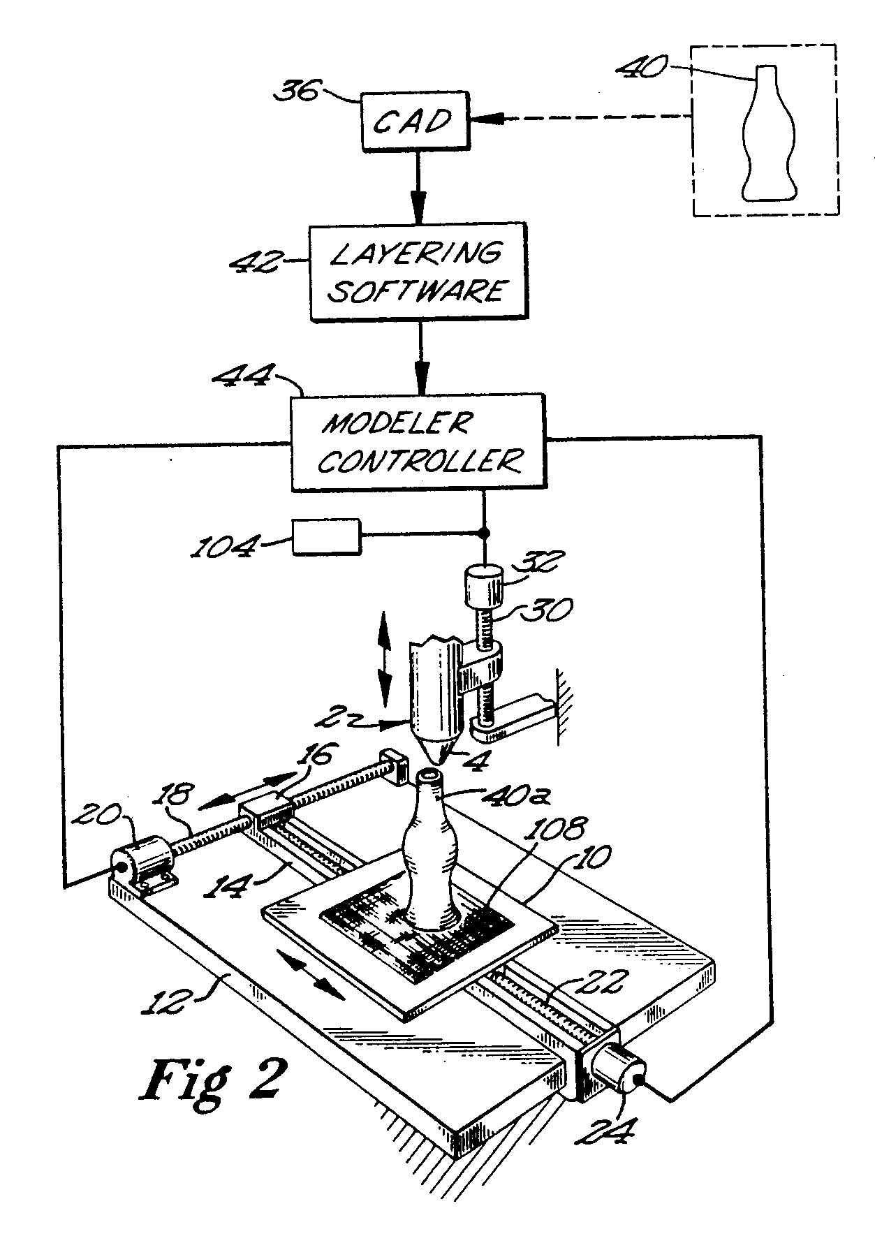
From Scott Crump’s original patent for FDM: axes 18 and 22 (XY) control the process direction while axis 30 (Z) controls the build direction. I learned this terminology while leading software research for his numerous “skunkworks” projects at Stratasys.
When both the build and process directions must conform to a curved surface, the natural representation becomes a scalar field (a function defined at every point on the surface that encodes distance, parameterization, or some other varying quantity). In some cases these fields are smooth, but they can also include discontinuities that must be tamed to achieve high quality results and ease-of-use.
Using this analytical framework of build and process directions, let’s explore computational design with VEER and LOOP where, unlike in usual 3D printing, they may not be orthogonal:
RLP VEER
For RLP, the basic idea is to find the start and end of a tube to establish the build direction field. For closed tubes, like prosthetic liners, we want to end on a point, which we can think of as a special case where a tube has one end collapsed to a point.
As the first step of geometry processing, VEER finds all the open loops in a surface and uses different strategies depending on the count of inner loops. In the case of one or two loops, VEER creates a set of contours that interpolate cleanly between one loop and either a distal point or the other loop. Higher genus topologies (more holes) require segmentation. This field or list of fields defines the build direction.
To construct the process direction field, we take closed isocurves of the build parameterization and align their periodic seam. To produce a toolpath, we “spiralize” a those contours into a helical topology, like FFF vase mode in 3D. Both versions of VEER help designers visualize and control how the variable toolpath affects surface finish and production rates.
RLP VEER On offers a straightforward, linear workflow for gravity free manufacturing.
V3D LOOP
LOOP’s parameterization process starts by specifying the knitting direction on a surface without seams. If your mesh has holes, LOOP lets you use curves as seam cuts to produce flat topology with seam allowance for assembly. One or more curves then define the build direction. LOOP uses those curves to construct the process direction field, with gradient approximately in the direction of carriage travel, transverse to the build direction. The needles on the machine are evenly spaced, so we construct a unit directional distance field that in the case of one curve simplifies to a geodesic distance field. If one thinks of the needle bed as a ruler, the process direction field has the magnitude of one needle’s span. In the parlance of knit engineering, “one needle” is a unit of length corresponding to the inverse of the needle’s gauge.
To create the build direction field, we need to accommodate surface curvature. Every knit row is about the same length, so we need to locally add or remove rows to relax the stretching energy that accumulates if flat knit. Consider the heel of a business sock for the line of “goring” aka “fléchage” that makes the sock L-shaped: the shortest rows appear anterior to the ball of the heel, increasing along the goring line. Therefore, unless the surface is intrinsically flat, LOOP knits incomplete “rows” or “courses” to build curvature, with a few different options for how to organize the placement of the goring singularities.
Simplified example of a sock knitting pattern, with the knitting direction left to right. The goring (red) is shown by the narrowing at the heel and the toe. The goring is held in place while the in-between part is knit, so the whitespace between the red curves becomes the goring line seen in the result. Note that socks are typically knit on circular machines where the blue edges are periodic.
Via discretization, we build a quad-dominated mesh with triangle pairs for goring and two different parameterizations in the build direction: a smooth version transferred from the original mesh and an integer coordinate that’s discontinuous across short rows (annotated with known actual neighbors). LOOP maximizes the orthogonality of the fields to minimize shear racking forces on the “bias” of the fabric. It also includes a system to automatically measure and manage swatches and calibrate and grade knit products.
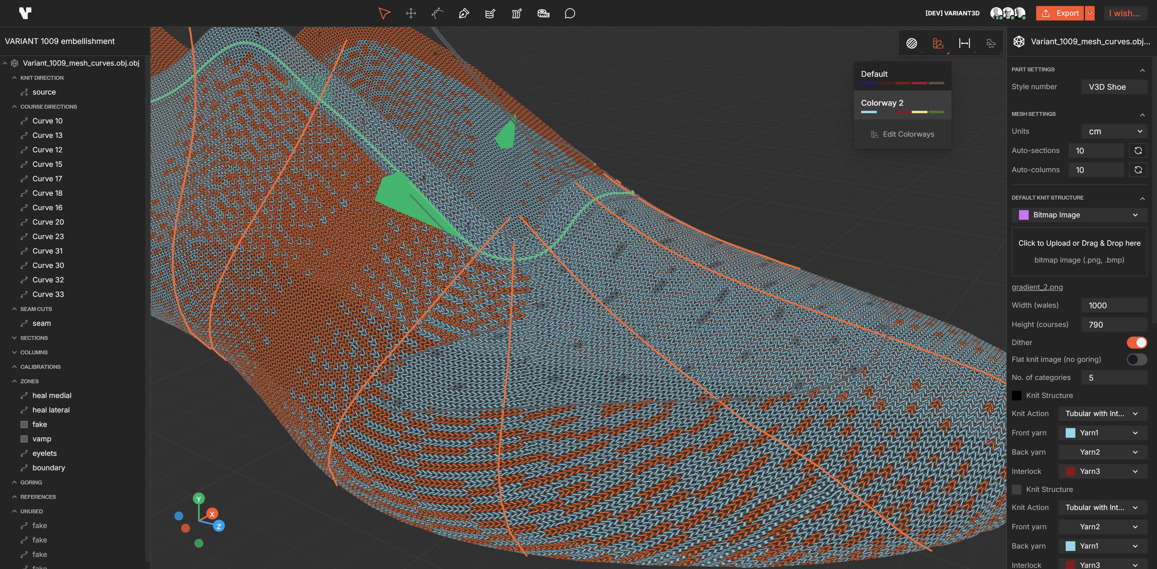
A footwear upper in V3D LOOP. The green curve specifies build direction, and the orange curves show rows that partition goring into sections. Both the structure patterns and the schematic rendering use GCL’s Omega modeling libraries.
Designed for computational design
While both LOOP and VEER are packaged so anyone can use the tech, we’ve also provided interfaces so power users can do pretty much everything RLP and V3D can do in house. Both offer new approaches to computational design, so the conversation became how to best provide the power to designers.
VEER Off: open 3D toolpathing in Grasshopper
VEER began its life as a set of Grasshopper components. After hardening the C++, consolidating mesh processing, and removing dependencies on other Grasshopper plug-ins, we had a common set of tools we could both use for internal needs and also share with our customers.
RLP printing offers several unique opportunities for customization. Advanced features include:
- Variable wall thickness, specified by a surface field or a pair of surfaces
- Variable hardness and or color in two dimensions
- Lattices based on surfaces or hexahedral meshes
- Surface features such as koosh-like fibers and soft loops
- Full control over position, feeds, and speeds.
With the Grasshopper-based VEER Off, led by Hesaneh Kazemi, you can do anything you want, down to line-by-line toolpathing. To allow both high and low-level geometry processing, we’ve added two new types to Grasshopper: RLP Mesh, which brings field annotated meshes, and RLP Toolpath, which includes parameters like stepover, feed rates, and speed. In particular, you can add curves to control the RLP Mesh’s fields by specifying terminal points and curves as well as constrain process directions in-between.
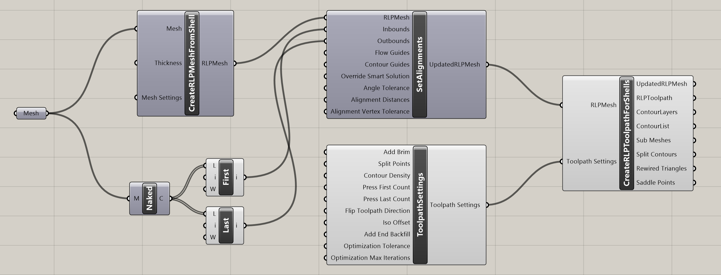 VEER Off component graph in Grasshopper.
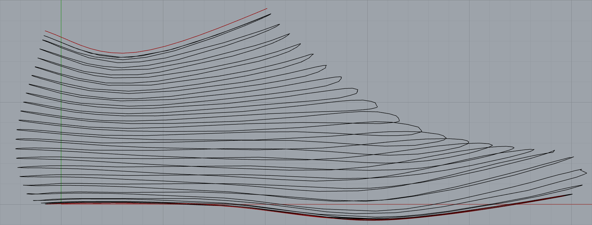 Resulting gravity free spiral toolpath on a curved surface.
LOOP: generative adversarial structures and knit actions
While tools like Grasshopper are also great at producing geometry for LOOP, which reads native Rhino files, in LOOP there are two challenges:
- We want to provide the full power of knitting, which allows users to not only drive a broad family of structures, but also change the goring topology a priori to have those structures come out perfectly. And, for the first time, we provide a WYSIWYG experience, driving the latent knit engineering expertise.
- Not all idealized structures are knittable. Knit engineers obsess over how various structures interact to maximize both performance and speed of knitting. Different hardware has different capabilities and trade-offs. How can we validate the idealized designs against hardware constraints and input formats to enable easy prototyping with a direct path to production?
For those of us who have used CAD, we’ve all had the aha moment when we learn to break down the world into the language of CAD. The team at GCL comes from a strong background in language and IDE design, so we tend to model the world with code and compilers. GCL’s tools are sort of like CAD software for data, it’s like CAD, but made out of custom languages and compilers, and often compiling down to CAD or CAM.
In this case, we chose Python and created a sort of generative adversarial system: the designer proposes idealized structures, and the machine pushes back with manufacturing reality. On the generative side, the Structure Platform is aware of many spatial parameterizations, including the fields shown above, 3D position, and signed geodesic distance to open and closed curves. A computational designer can then program patterns using any of these input drivers, with helpers to make it easy to handle patterns across parametric discontinuities and to place goring singularities where they are least disruptive. It works like a fragment shader on the cloud: Each knit cell can be single or double jersey while alternating between several yarns, also adding holes like pointelle, inner channels via tubular knitting, and surface bumps via ottoman.
Downstream, the adversarial Yarnpather plays the role of the knit engineering expert. It chooses a strategy that works with the destination hardware, optimized for prototyping or ready for production. The user can then see if the Yarnpather was too disruptive and iterate the structures.
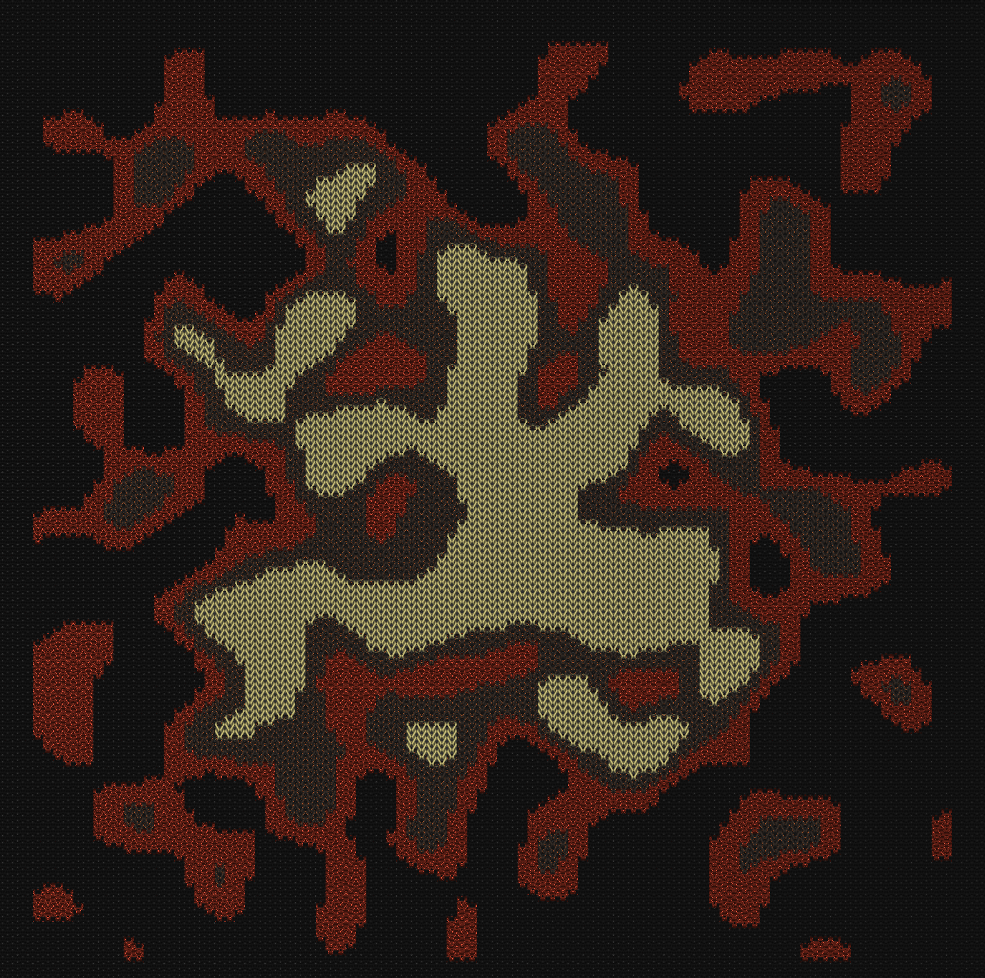
LOOP’s Structure Platform lets computational designers create field-driven textures via several 2D and 3D parameterizations via UGF modeling and standard python libraries. (Click to expand)
A shared commitment to openness and extensibility
Both CTOs, Bjørn at RLP and Will at V3D, brought a passion for openness with these tools. VEER Off will soon be available for use with any hardware as well as the enormous ecosystem of Grasshopper components. I’ve been particularly enjoying extending Daniel Piker’s Isopod plugin to bring implicit modeling to certain build processing challenges.
Meanwhile, LOOP’s Python-based Structure Platform means the entire ecosystem of scientific computing, including noise and texture libraries, bitmap processing, text layout, and advanced processing in numpy and scipy, is available to designers. We also included Omega, GCL’s UGF modeling libraries, for shape drawing on curved surfaces.
Geodesic distance modeling via unit gradient fields
The actual algorithms used to construct the fields in LOOP and VEER include hard-earned, domain-specific knowledge that are too nuanced for this blog post. That said, for computational designers interested in getting a feel for some of these approaches to inducing surface parameterization, let’s construct a field similar to the RLP build direction using UGFs, an abstraction of SDFs that also applies to geodesic distance fields. In particular, we’ll use the two body field to interpolate from one open edge to the other.
The first step is to compute geodesic distance fields to each open contour \(A\) and \(B\) on the surfaces. How to represent them? Let’s do the easiest thing and store the scalar values on each vertex. Our boundary curves share the same vertices, so we can use a computational approach that only relies on vertices.
In the results, we see a challenge with the simple approach: the geodesic distance field from the bottom curve develops a sharp region on the vamp of the upper (top of the foot). That discontinuity will carry through to the fields we’re about to derive.
Before we compute the two body field, take also a look at the sum and difference fields, which are always orthogonal for UGFs. The sum varies as the distance between curves varies. The difference field includes the medial curve, which also exists in the two body field.
Notice that VEER uses a smooth solution that resembles the two body field but does not show a discontinuity on the vamp.
With that setup, we have demonstrated basic 3D toolpathing. In Grasshopper, tools like Kangaroo 2 can help find smoother alternative parameterizations by relaxing stretching energy across the mesh, though the details of VEER and LOOP’s proprietary approaches go well beyond what Kangaroo offers out of the box.
Summary
LOOP and VEER represent a new category of software we might call “surface field modelers”: tools that construct and manipulate scalar and vector fields on curved surfaces to drive manufacturing processes. Both emerged from the same insight that discrete differential geometry, particularly distance-like fields on surfaces, can bridge the gap between arbitrary 3D shapes and the constraints of emerging advanced fabrication methods.
For RLP, the challenge is constructing smooth, continuous spiral toolpaths on surfaces of arbitrary topology, respecting angle constraints and enabling multi-segment sequencing for complex shapes. VEER solves this challenge by building parameterizations from intrinsic surface analysis, starting with the build direction and deriving process direction from regularized isocurves.
For V3D, the challenge is mapping a designer’s intent onto a knitting machine’s non-uniform integer grid of needles and rows, accommodating curvature through goring and providing a programmable structure platform. LOOP solves this by starting with the process direction via geodesic or unit directional distance fields, then constructing the build direction with short-row insertions where Gaussian curvature demands them.
Both products share a dual-audience strategy: cloud interfaces for ease-of-use alongside open, extensible tools for computational designers, and both demonstrate that when you get the math right, the software can compress design cycles from months to minutes.
Unit gradient fields provide a first order approximation of the algorithms across both domains: the same two-body field that interpolates between boundary curves for RLP toolpathing can parameterize knit wales for V3D. As these manufacturing processes mature and new ones emerge, we expect surface field modeling to become an increasingly important discipline at the intersection of geometry, manufacturing, and design.
Technical notes
The 3D interactive models were directly generated from VEER and LOOP’s debug output, including LOOP’s quad-dominated mesh with goring triangles. Both VEER’s process direction and LOOP’s continuous build direction field needed to be reconstructed from curves, which explains some of the noise along the back seam.
I wasn’t initially able to get an existing geodesic “heat method” Grasshopper component running, but Claude provided this Python component for Grasshopper.
Two different PLY files hold the fields for the VEER and LOOP meshes, and Claude Code mostly provided the THREE.js based viewer and custom fragment shader. For fidelity, the field values are stored as floats, which is not conventional for PLY viewers.
Postscript
Thanks to Will, Bjørn, Hamilton, Hesaneh, and the GCL team for the inspiration and feedback. After roughly two years on these projects, I’m able to proudly step back from running scrum teams to more strategic and advisory work. The GCL team continues to be active in both residencies, although some new projects are warming up, including Omega and Implicit Space (more soon).
Meanwhile, after the launch of VEER, Hamilton moved to NYC and became a V3D customer. Two V3D machines currently reside at MIT’s Self Assembly Lab from which RLP was borne. Perhaps we’ll see more convergence from RLP and V3D in the future. As advanced manufacturing advances towards more production use, I suspect we’ll see more surface modelers like VEER and LOOP produce the output.
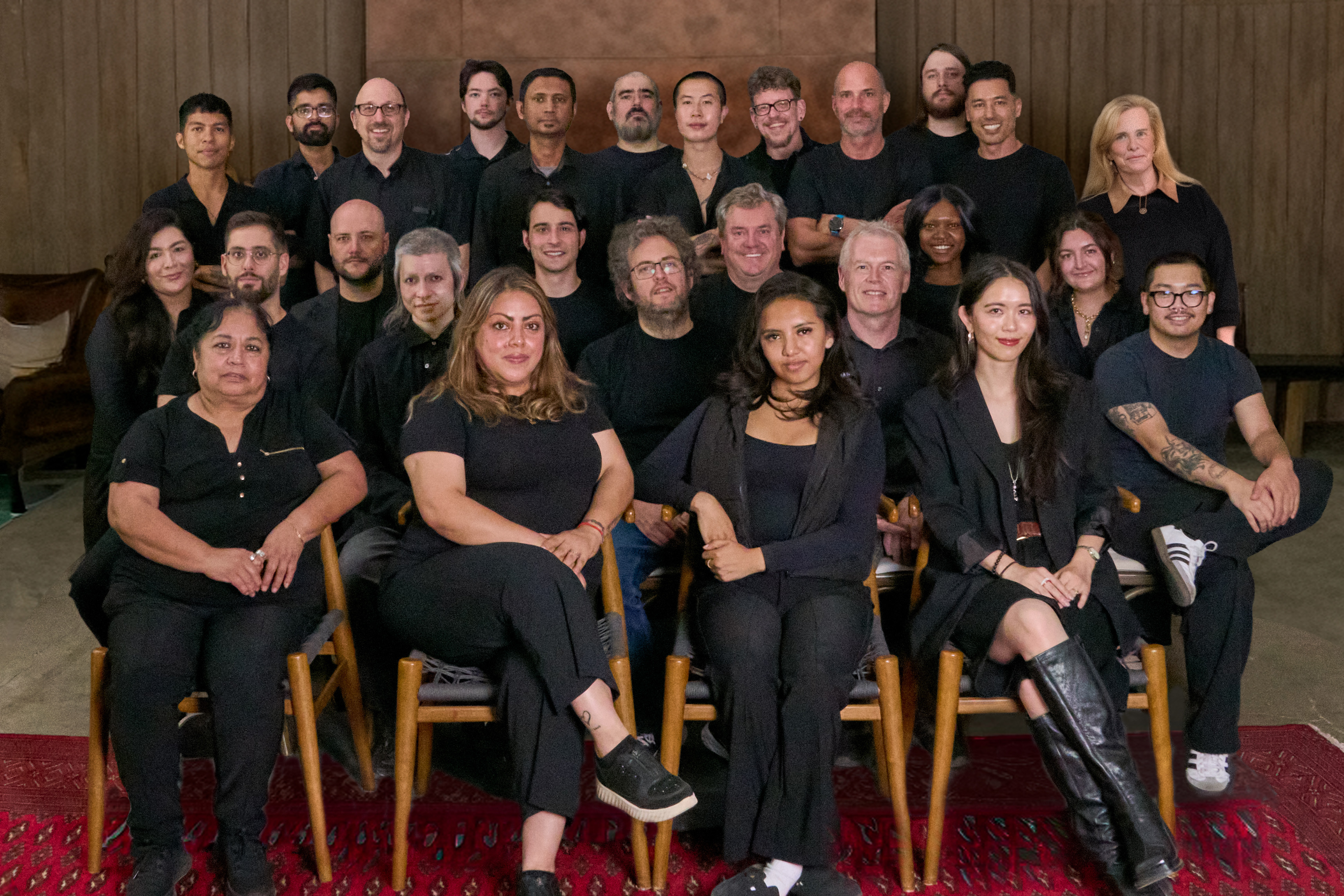
The teams behind the technology: Rapid Liquid Print (left) and Variant3D (right).